Here You Can Find Too Many Things Which Help You Too Much!!! In Your Own Language

Saturday 16 May 2015

Adding Fonts in Revit

Adding Fonts in Revit

Adding Fonts in Revit

Currently, Revit supports all installed True Type®, ANSI fonts. If these fonts are loaded you computer, you can use them in Revit. 

To load fonts:

1.                     On the Windows Control Panel, click Fonts.

2.                     Select File - Install New Font.

3.                     Install the font on the system.

For some True Type fonts, there are some problems with text output into PDF files in Revit PDF Writer. The source of problem is the older style TrueType fonts. Since the introduction of TrueType technology, Adobe and Microsoft have made additional improvements and now support OpenType fonts. For more information, read the article about OpenType fonts.
Tests indicate that newer OpenType fonts work better with Revit PDF Writer. If you look in the Windows Fonts directory, you will see older TrueType font files shown with the letter "T." OpenType fonts are shown with "O." Most of fonts installed by Windows are now OpenType
Read More

Phasing, Phase Filter and Phase

Phasing, Phase Filter and Phase

Here is my attempt to explain Phasing and Phase Filters.. a very complicated thing to try and explain and this is a primer to help you understand it better.
When encountering a project with existing construction I write a description of the 3 Phases we need for any Project, namely an existing phase for the existing base conditions and a demolition phases for modification to existing and construction/renovation for any changes after.  The description will help explain each phase of construction/destruction.

If were just doing New Construction (all in one phase) the other phases are irrelevant.

If your doing New Construction in multiple Phases you can add it here such as New construction Phase 1, New construction Phase 2 etc...

Then I add to the Phase Filter Names to make them easier to understand.

By adding "In Current Phase" to the "Filter Names" to remind you what you are looking at, for example: Show Previous + Demo (In Current Phase) means that you will see the complete work in the phases preceding the active phase...as well as demolition in this active phase.

More on this latter...


I then override the Cut Line Graphics of the Demolished Phase so it shows up bold.

This imitates standard Architectural convention.

Currently the default is to be grayed out.

This allows me to clearly show what part of the building has been demolished in each view.

Close this dialog box and go to your floor view.

Now you can add more Phases of New Construction, as mentioned above, as required. You can also add more Phase Filters but we have found that given the 7 combinations that Revit gives you is more than adequate. 

Now that we have established the Project Phase it's time to look at how to apply them to our views.

If you are doing a Renovation/Addition project you'll need to create multiple Duplicate Views. We do this so we can easily represent each phase (Existing, Demolition and New Construction) on each view.

We also need to set the Phasing for each view.

Here is an example of how the View and the Phase Filters and Phase selections are used.


Existing View

With any Renovation/Addition project you need to know what Existing Building you are dealing with, in this View you'll draw the existing building.

Your Existing View Phasing should be set as follows.


Phase Filter will be set to Show New, only because there is no previous phase.
The Phase is Existing because that's what your currently creating, so an existing building in the real world is "New Construction" in "Existing" Phase....confusing I know!
Existing View show the existing building.

Once you have the existing building modeled, Duplicate the view and rename it toDemolition.


Demolition View

This view you'll use the little hammer icon on the Phasing panel on the Manage Tab and hit the stuff that is to be demolished. Duh!

Notice that if your demolishing an existing wall that has doors or windows you will have to demolish those as well (if they're being demolished as well that is).

Your Demolition View Phasing should be set as follows.


Phase Filter will be set to Show Previous + Demo, as you want to show the Previous phase which is Existing and the Demolition occurring in the active "Demolition" phase.
The Phase is Demolition because that's what your currently creating.


Demolition View show the existing building and any components of the existing building that are to be Demolished.
Once you have the Demolished view created duplicate the view and rename it to New Construction.


New Construction View

This view you'll start placing walls and components that are part of the projects New Construction.

Your New Construction View Phasing should be set as follows.


Phase Filter will be set to Show Previous + New, as you want to show the Previous phase which is what will be remaining of the Existing Building minus the Demolition as well as the New construction.

What is shown in "Show Previous" is the "Completed work" for all phases preceding the current phase. So what we are looking at is Existing (completed) and Demolition (completed) plus New Construction.

The Phase is New Construction because that's what your currently creating.


New Construction View should clearly show the New construction as well as the existing building after demolition has occurred.

Note: Any model objects you create while in a specific Phase will be part of that Phase, thus controlled by the Phase filters.


Filters not only apply to Plan Views but also too your other views including Sections, Elevations and also 3D Views.
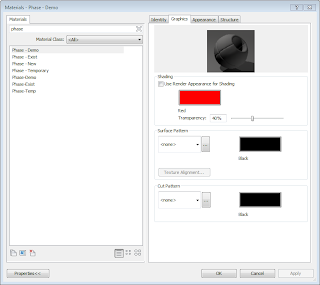
When you Shade the view the Material assigned to the Phase Status now comes into to play.


If you look Under Materials you'll find phase materials for each Phase. These Materialshave colour shading assigned to them to clearly show each phase.


Also... Thanks Adam for reviewing this document for me and adding your thoughts. I felt it to be such a difficult subject to document,  I appreciate Adams input.
Read More

How to Create a Material Take Off

How to Create a Material Take Off

Here are the steps for creating a basic Material take off schedule in your Revit Project.

For this example I'll be using the components of an Exterior Brick on metal stud wall and quantify the amount of Brick in a project.

To start a Material Take off:

1.       Click View tab > Create panel > Schedules drop-down > Material Takeoff. 

2.       In the New Material Takeoff dialog, click a category for the material takeoff schedule, (in this case Wall), then name your Schedule, and click OK.


3.       In the Material Takeoff Properties dialog, for Available Fields, select the material attributes. Such as Area, Description, Name (Volume if you require such in the case of Concrete. Sort the list in order accordingly.

4.       Use the filter to specify which material(s) you want to schedule.


5.       Sort by Material Name, specify a Grant total if you would like to itemize every Instance. By itemizing every Instance you can quickly and easily use the “Highlight” in Model tool to see the location of the material.

6.       Under “Formatting” you will need to check the “Calculate Totals” box where volumes or areas are required.


The material takeoff schedule displays, and the view is listed in the Project Browser under Schedules/Quantities. 

Tip: When creating a flooring material take off create the floor finish as a separate floor, this way you can pull the material take off of the overall floor sub-assembly separate from the individual room or area floor finishes. For example typical wood frame floor assembly we can quantify the amount of plywood sheathing required as well as the area of carpet or tile on top of the subfloor.
Read More

Revit Structure 2012 Keyboard Shortcuts

Revit Structure 2012 

I have updated my list of common Revit Keyboard commands.
These are the most common used commands with Keyboard shortcuts.


Revit Structure 2012 Keyboard Shortcuts

Here it is...

·         AL = Align

·         CM = Place Component

·         CO = Copy

·         DI = Dimension

·         DL = Detail Line

·         DM = Draw Mirror point

·         DR = Door

·         DE = Delete

·         ER = Editing Request

·         EW = Edit Witness Lines

·         GR = Grid

·         GP = Create Group                                     

·         LI = Model Lines

·         LW = Line work

·         MA = Match Properties

·         MD = Modify

·         MM = Mirror (along reference plane)

·         MO = Modify

·         MV = Move

·         OF = Offset

·         PN = Pin

·         PP = Properties

·         RE = Resize (Scale)

·         RH = Reveal Hidden Elements

·         RM = Room

·         RO = Rotate

·         RT = Room Tag

·         RL = Reload Latest

·         SE = Snap End

·         SL = Split Elements

·         SM = Snap Mid

·         SO = Snap Off

·         SP = Snap Perpendicular

·         SQ = Snap Quadrant

·         SS = Turn off overide

·         SU = Sun Settings

·         SX = Snap Points

·         SZ = Close

·         TG = Tag

·         TL = Thin Line

·         TR = Trim (Fillet, Trim Extend)

·         TX = Text

·         UP = Un-Pin

·         UN = Project Units

·         VG = Visibility Graphics

·         WA = Wall

·         WN = Window

·         WT = Window Tile

·         ZA = Zoom All (Used with tiled windows)

·         ZF = Zoom Fit

·         CTRL +S = Save

·         CTRL+O = Open

·         CTRL+Z = Undo

·         CTRL+Y = Y Redo


CTRL = to add to selection

SHIFT = to subtract from selection or force horizontal or vertical

TAB = Cycle through selection or snaps
Read More

Recent Posts